The Problem:
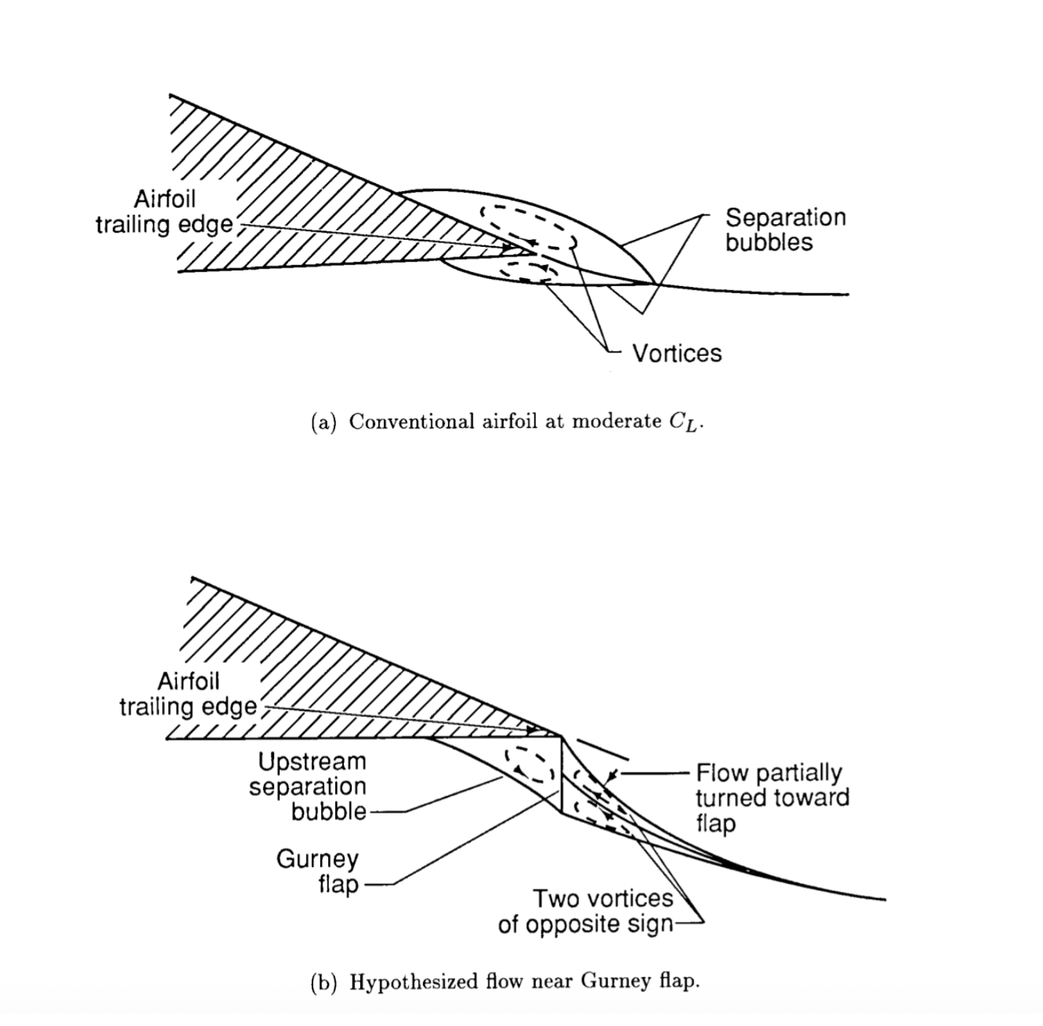
Gurney flaps are small, right-angle tabs added to the trailing edge of a wing. They are a well established technique in aviation for increasing downforce, but their effect on drag and their optimal sizing relative to wing chord length aren’t one size fits all. For Northeastern Electric Racing’s front and rear wings, the question was whether Gurney flaps could meaningfully increase effective airfoil area and downforce without an unacceptable drag penalty for our specific wing geometry.
Research & Design:
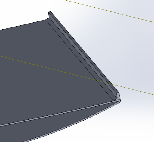
I led the initial research phase, studying how Gurney flaps are used in aviation applications and adapting that logic to our car’s wings. From there, I designed multiple flap height variants in Solidworks, sized relative to the wing’s chord length, to test across a range of geometries rather than committing to a single configuration upfront.
Analysis:
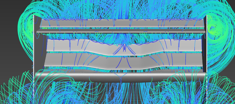
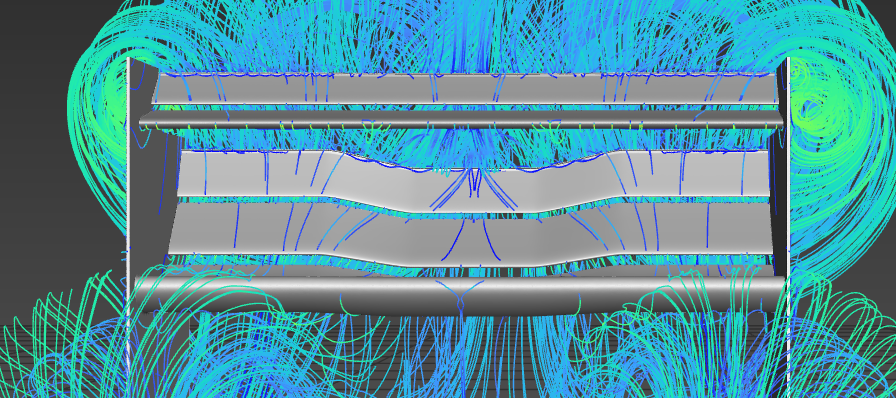
Each flap variant was tested using ANSYS CFD to visualize airflow behavior and quantify resulting downforce and drag. The CFD results showed that our tested configurations produced high downforce, but paired with a significant drag increase. This tradeoff needed optimization, however did not constitute termination of the project.

Status:
Based on these results, the next planned step was running further CFD trials varying flap height, thickness, and angle to find a configuration that preserved the downforce gain while reducing the drag penalty. I stepped back from this project as my involvement with other clubs and coursework grew, before that next optimization round was completed. The groundwork feasibility research, initial geometry design, and baseline CFD is documented here as a foundation for any future continuation of this work.